Image Formation and Camera Model
How a 3D physical world is mathematically projected into a 2D pixel array, forming the foundation of computer vision and multi-view geometry.
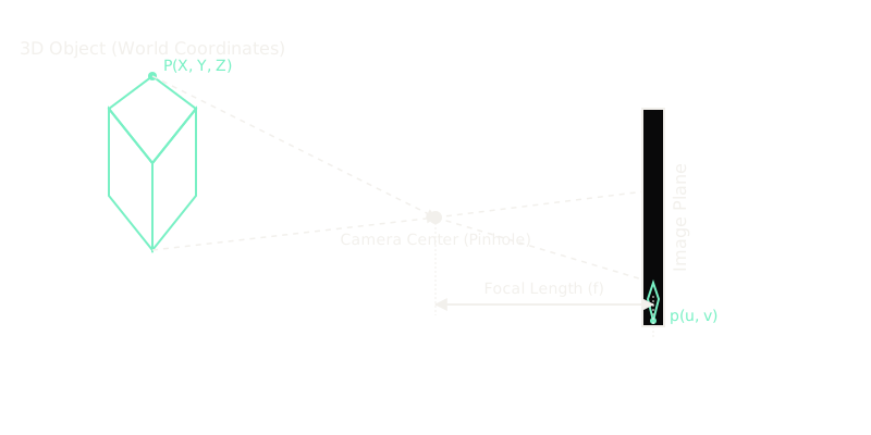
Why Does This Exist?
In computer vision, the fundamental problem is that images are flat, but the world is not. Every photograph represents a massive loss of information—an entire three-dimensional dimension is crushed down to a two-dimensional grid of light intensities.
To build autonomous vehicles, 3D reconstructors, or augmented reality systems, we must understand exactly how that loss happens. The camera model is the mathematical bridge that allows algorithms to relate the coordinates of a pixel on a screen to the physical location of an object in the real world. Without a rigorous model of image formation, a self-driving car would see a pedestrian in an image but have no geometric basis for determining whether that pedestrian is ten feet away or a hundred.
Think of It Like This
A laser pointer shining through a keyhole
Imagine standing outside a dark room holding a laser pointer, pointing it through a tiny keyhole in the door, aiming at the opposite wall inside. The point where the laser hits the wall depends purely on your position, the angle you are aiming, and the distance from the keyhole to the wall.
In a pinhole camera model, light from the world acts like millions of tiny lasers. They all travel through a single keyhole (the camera center or aperture) and strike a wall (the image sensor). If the wall is further away (a longer focal length), the image gets stretched out, making objects look larger. If the wall is closer, you capture a wider field of view.
How It Actually Works
The projection of the 3D world into 2D pixels relies on a sequence of coordinate transformations.
1. World Coordinates to Camera Coordinates (Extrinsics) An object exists in a global 3D space, . The camera is located somewhere in that world, pointing in a specific direction. The extrinsic parameters define this relationship via a rotation matrix and a translation vector : represents the 3D point relative to the camera center, with the Z-axis pointing straight out from the lens.
2. Perspective Projection Once the point is relative to the camera, light travels in straight lines through the camera center to the image plane. Under the pinhole camera model, similar triangles dictate the projection. A 3D point projects to a 2D continuous point on the image plane located at a distance (the focal length) from the camera center: This division by creates perspective: objects further away (larger ) project to smaller coordinates on the image plane.
3. Image Plane to Pixels (Intrinsics) The continuous coordinates are in millimeters or meters. Digital images use discrete pixels. The intrinsic parameters matrix converts these metric coordinates into pixel indices , accounting for the sensor's pixel width and height (often wrapped into ) and the principal point , where the optical axis intersects the image plane:
4. The Unified Matrix Equation Using homogeneous coordinates (appending a 1 to vectors to allow matrix multiplication for translation), the entire pipeline from 3D world to 2D pixel becomes a single matrix multiplication: Or more compactly: .
Code
import numpy as np
def project_3d_to_pixel(point_3d_world, K, R, T): """ Projects a 3D world coordinate into a 2D pixel coordinate. """ # 1. Transform world coordinates to camera coordinates (Extrinsics) # P_cam = R * P_world + T point_3d_cam = R @ point_3d_world + T X, Y, Z = point_3d_cam[0], point_3d_cam[1], point_3d_cam[2] # Avoid division by zero if point is directly at the camera center if Z == 0: Z = 1e-6 # 2 & 3. Project to image plane and convert to pixels (Intrinsics) # We can do this directly with the intrinsic matrix K # [u*Z, v*Z, Z]^T = K * [X, Y, Z]^T homogeneous_pixel = K @ point_3d_cam # 4. Normalize by Z to get actual u, v coordinates u = homogeneous_pixel[0] / homogeneous_pixel[2] v = homogeneous_pixel[1] / homogeneous_pixel[2] return np.array([u, v])
# Example usageK = np.array([[800.0, 0.0, 320.0], # fx, 0, cx [0.0, 800.0, 240.0], # 0, fy, cy [0.0, 0.0, 1.0]])R = np.eye(3) # No rotationT = np.array([0.0, 0.0, 5.0]) # Camera is 5 units away along Zpoint_world = np.array([1.0, 2.0, 10.0])
pixel_coord = project_3d_to_pixel(point_world, K, R, T)# -> [ 373.33333333, 346.66666667]Watch Out For
Ignoring lens distortion
The mathematical pinhole model assumes light travels perfectly straight and the lens introduces no artifacts. Real lenses suffer from radial distortion (straight lines appearing curved, especially near edges, known as a "fisheye" effect) and tangential distortion. If you do not un-distort your image before running SLAM or 3D geometry algorithms, your matrix equations will be violently incorrect near the borders of the image.
Negative Z (Behind the camera)
The basic projection equation happily projects points behind the camera () into valid pixel coordinates, as if they were mirrored in front of the lens. Always check that the coordinate in the camera frame is strictly positive before rendering or considering a point "visible" on the image plane.
The Quick Version
- Image formation collapses a 3D physical world into a 2D pixel array, losing depth information.
- The Extrinsic matrix () maps the 3D world to the camera's local 3D perspective.
- The Intrinsic matrix () projects that local 3D perspective onto a 2D image sensor and translates metric distances into pixel indices.
- The pinhole camera divides by depth , meaning objects shrink in the image as they move further away (perspective projection).
- By calibrating a camera, you determine its matrix, which allows you to run computer vision algorithms that understand real-world geometry.