Visual explainer
Actuators, Gearing and Torque Limits
Follow motor current through a gearbox to joint torque, then check speed, heating, backlash and whether a reachable load can actually be held.
An actuator turns supplied energy into mechanical effort. A gearbox can increase a motor's output torque by reducing its speed, but the joint must still satisfy current, voltage, thermal and mechanical limits. Reaching a pose does not establish that the robot can hold a load there.
This page uses a hypothetical electric drive, not a manufacturer's specification. Torque means rotational effort, measured in newton-metres (Nm); angular speed is in radians per second (rad/s). We use positive magnitudes in the motoring direction and explicitly change scales between diagrams.
1. The Load Sets Demand
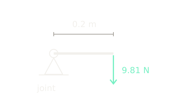
A 1 kg payload hangs 0.2 m horizontally from a joint. Gravity supplies N, so balancing the load requires Nm. The link's 200 drawing units represent 0.2 m; the force arrow identifies direction rather than a second length scale.
The perpendicular distance to the force's line of action matters. If the link rotates upward by angle from horizontal, payload holding torque becomes , reaching zero when the load sits directly above or below the pivot. We neglect link weight, friction and acceleration here. Those add demands; this payload-only calculation is not a complete actuator sizing result. The robot anatomy visual connects these moments to a multi-joint arm.
2. Current Creates Motor Torque
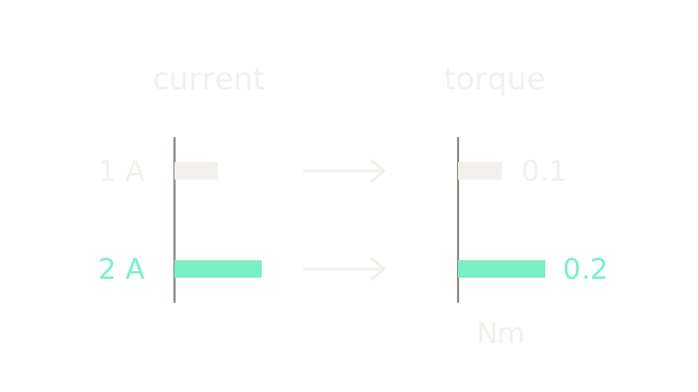
For our simplified motor, the torque constant is Nm/A and electromagnetic torque is . One ampere gives 0.1 Nm; two amperes give 0.2 Nm. Each column uses its own units, so equal-looking bars show proportional changes rather than equality between amperes and newton-metres.
This is electromagnetic torque before subtracting mechanical losses. Applied voltage must also overcome winding resistance and the back electromotive force generated by rotation. A request for more current cannot be met at every speed with a finite supply. Brushless drive conventions matter too: phase-current definitions, commutation and torque constants must agree. Modern Robotics 8.9 explains the electric motor and geared-joint model.
3. Trade Revolutions For Reduction
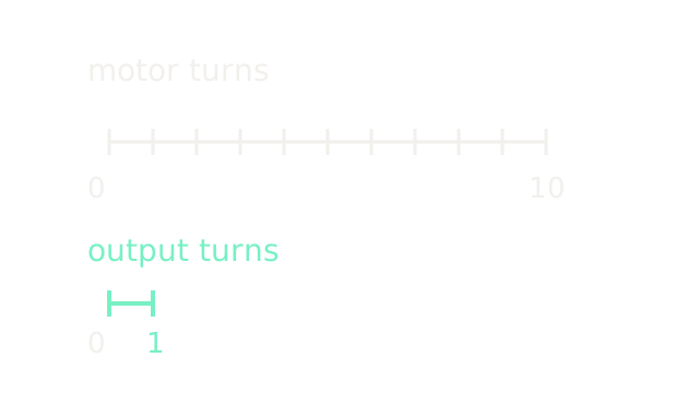
Define reduction ratio . Ten motor revolutions therefore advance the output by one revolution. Both rulers use 40 drawing units per revolution.
The kinematic relation is . It holds independently of the efficiency model while the teeth remain engaged and deformation is neglected. Rotation signs depend on the transmission arrangement; the page compares magnitudes. A single pair of external gears reverses direction, while another gear stage can reverse it again.
4. Torque Rises, Speed Falls
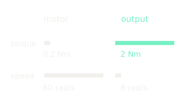
Start at motor torque 0.2 Nm and speed 80 rad/s. An ideal 10:1 gearbox produces 2 Nm at 8 rad/s. Torque bars use 100 drawing units per Nm; speed bars use 2.5 drawing units per rad/s. Compare lengths within a row.
Mechanical power is : input power is W and ideal output power is W. Reduction transforms the operating point; it does not supply extra power. A higher ratio is useful only if the resulting output speed still meets the task. Northwestern's motor and gearing guide derives this power balance.
5. Losses Reduce Delivered Effort
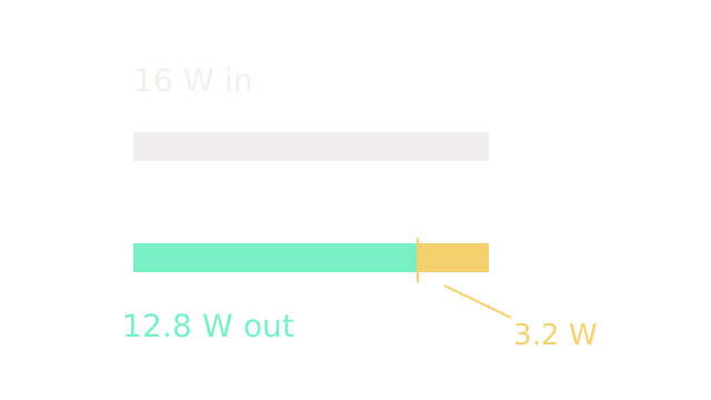
Assume forward mechanical efficiency at this operating point. Of 16 W entering the gearbox, W reaches the output and 3.2 W is lost. The bar partitions those quantities on one scale: 20 drawing units per watt.
At output speed 8 rad/s, delivered torque is Nm, equivalently . Actual efficiency varies with speed, load, lubrication and direction. At zero speed, the power ratio is undefined; extending this constant-efficiency torque relation to holding is an illustrative approximation. Reverse power flow and static friction require their own model.
6. Check The Operating Envelope
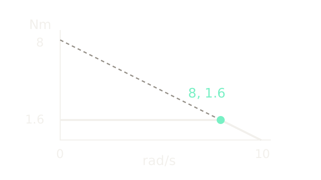
For a simplified fixed-voltage DC motor, assume no-load speed 100 rad/s and ideal stall torque 1 Nm. Its voltage-limited line is . Transforming through our gearbox gives the dashed output line Nm. The assumed 2 A current cap independently restricts output torque to 1.6 Nm. The solid boundary is the lower of those two limits for positive motoring.
At 8 rad/s, the limits intersect: Nm. At 9 rad/s, the voltage limit permits only 0.8 Nm even though the current cap is unchanged. The 8 Nm intercept of the dashed line is hypothetical voltage-limited stall torque; the drive cannot reach it with the current cap. This is an electrical envelope, not permission for continuous operation. maxon's motor-model reference also explains why real speed-torque curves need not be exactly linear.
7. Heating Depends On Duty
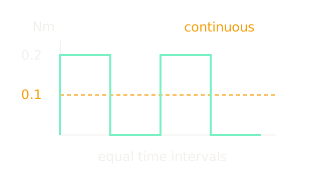
Now assume a continuous motor torque rating of 0.1 Nm and a permitted intermittent torque of 0.2 Nm. The trace alternates equal intervals at 0.2 and zero; the dashed amber line marks the continuous rating. This is motor-side torque, not joint torque.
The mean torque is 0.1 Nm, but copper heating depends on current squared. With constant , the equivalent RMS torque is Nm, exceeding the assumed continuous rating. Under a simple cycle-averaged thermal model, 0.2 Nm pulses need duty fraction no greater than to meet that RMS limit.
Even that calculation needs an additional check: individual pulses must respect peak-current limits and the motor's thermal response. Cooling, winding temperature, mounting and cycle length matter. Holding at zero speed still consumes current and generates winding heat. A stall-torque number is not a continuous holding-torque rating.
8. Reduction Reflects Rotor Inertia
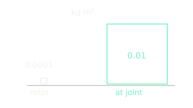
A rotor turning times faster than the joint stores kinetic energy . Rewriting this in joint coordinates gives apparent inertia . With kg m² and , the joint sees a 0.01 kg m² rotor contribution.
Square areas encode inertia: the larger square has ten times the side length and one hundred times the area. At joint acceleration 5 rad/s², accelerating that reflected rotor alone requires Nm, before load inertia and friction. More reduction can improve static torque while making rapid motion and low-effort backdriving harder. This ideal energy model excludes gearbox inertia and transmission compliance.
9. Reversal Exposes Lost Motion
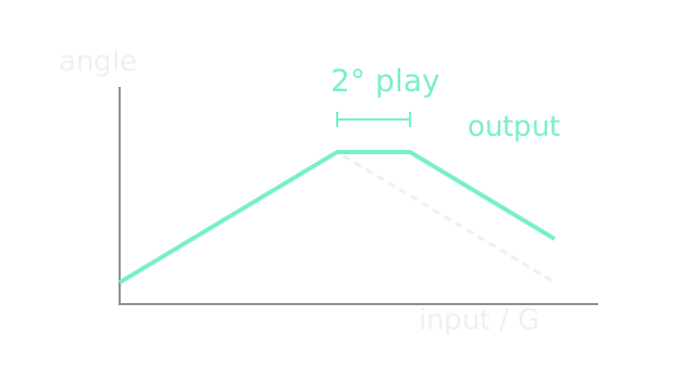
The dashed input trace is motor angle divided by G, expressed in output-equivalent degrees. It first advances from 0° to 6°, then reverses. In this schematic backlash model, the output stays at 6° while input-equivalent angle falls from 6° to 4°. After the 2° gap is taken up, output motion resumes. Horizontal progression is illustrative; the trace predicts neither timing nor acceleration.
A motor-side encoder observes input rotation. Dividing that measurement by the nominal ratio cannot detect all output lost motion. Output sensing, preload or a lower-backlash transmission can help, with cost, friction or mechanical complexity. Actual response depends on load direction and elastic deformation; backlash is distinct from elastic twist, which changes continuously with torque.
10. Where It Breaks
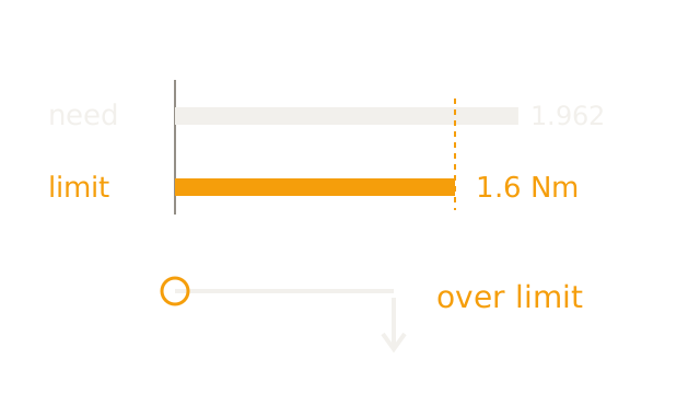
Return to the 1 kg load at 0.2 m. Required payload holding torque is 1.962 Nm; the illustrative output cap is 1.6 Nm. The bars share 160 drawing units per Nm, leaving a 0.362 Nm shortfall. Under this assumed static cap, the largest payload at that horizontal reach is kg, even before link weight. The lower continuous rating would be more restrictive for sustained holding.
Increasing controller gains does not create missing actuator effort. Changing the pose to shorten the lever, reducing the load, adding counterbalance or selecting another motor/transmission can change feasibility. Increasing reduction also changes speed, inertia and losses, so repeat the earlier checks. A brake can support a static load but does not supply arbitrary powered motion.
This drawing establishes that the assumed torque cap cannot balance the load. It does not predict whether protection trips, the arm moves or a brake catches it. For moving loads, include acceleration and coupled joint dynamics; continue with dynamics and impedance control.
The Quick Version
- Payload torque equals force times its perpendicular lever arm.
- Motor torque follows current under a consistent torque-constant convention.
- Reduction divides output speed by the gear ratio.
- Ideal torque gain preserves mechanical power.
- Transmission losses reduce delivered torque at a given speed.
- Voltage and current limits constrain the same operating point.
- RMS torque reveals heating hidden by mean torque.
- Reflected rotor inertia grows with the squared gear ratio.
- Backlash separates motor angle from output angle during reversal.
- Controller gains cannot overcome an insufficient physical torque limit.