Visual Measurement
Visual measurement turns pixel distances into millimeters with a calibrated scale, so a photo becomes a ruler you can audit.
Why Does This Exist?
Calipers touch and slow lines. Soft, hot, or sterile parts forbid contact. Engineers still owe tolerances in millimeters, not pixels. A raw pixel count means nothing without scale.
Visual measurement exists to supply that scale honestly. Input is an image plus a calibration that maps pixels to millimeters at the part plane. Output is lengths, gaps, and angles with an uncertainty note. The floor context is industrial vision; the pass fail gate is quality inspection. Camera geometry lives in camera calibration.
Use it when parts allow a clear view of the measured edge. Use contact gauges when edges hide inside bores or transparency lies.
Think of It Like This
A photocopy with a coin for scale
You photocopy a leaf with a coin beside it. The coin width is known, so leaf pixels divided by coin pixels per millimeter give leaf size. Move the leaf off the glass and the scale breaks.
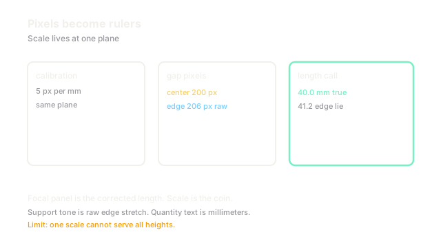
Calibration is the coin on the same plane. Telecentric optics keep the copier flat. The analogy stops at depth: coins and leaves share one plane while real parts curve, so one scale number cannot serve all heights.
How It Actually Works
Place a calibration target at the part plane and solve pixels per millimeter plus lens distortion. Undistort, locate subpixel edges along the profile, then convert: . A pixel gap at pixels per mm gives mm. Uncertainty adds edge noise plus calibration residual plus thermal drift. Telecentric lenses hold steady with height; standard lenses let perspective shrink far edges.
Worked example
A shaft gap spans pixels at center where . Length mm. The same gap near the image edge spans pixels before undistortion because radial stretch magnifies it. After correction it returns to pixels and mm. Without correction the edge reads mm, a mm lie that fails a mm tolerance.
Watch Out For
Perspective sold as scale
One from the table center applied to a tall part mixes two depths. The symptom is diameters that grow with height. Fix it with telecentric optics or per height calibration, and state the valid depth range on every report.
Edges chosen by threshold, not physics
A global threshold on a soft shadow edge moves with exposure by pixels. At pixels per mm that is mm of fake variation. Fix it with calibrated edge models, fixed lighting, and exposure locked after calibration.
The Quick Version
- Visual measurement maps pixels to millimeters at the part plane.
- Length where is pixels and is pixels per mm.
- The fixture reads mm true against mm uncorrected at the edge.
- Undistort and state depth range or tall parts lie.
- Lock light and exposure after calibration or edges wander.