Robot Perception: Depth to Usable Geometry
Raw depth sensors measure distance along camera rays, but robots require spatial physical geometry: point clouds, voxel grids, or signed distance fields with an explicit distinction between observed free space and occluded unknown space.
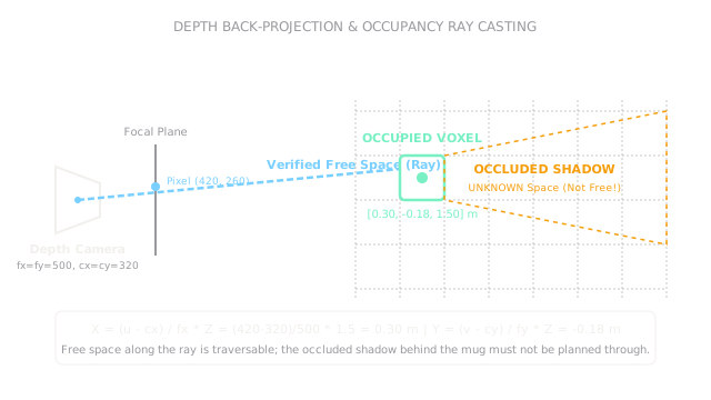
Why Does This Exist?
In computer vision, a depth image is an array of scalar numbers representing distance. For generating 3D models or graphics, visualizing that surface is often enough. But an autonomous mobile robot or robotic arm cannot plan motion solely with a 2D depth map: it must know which regions of 3D space are guaranteed empty, which contain solid obstacles, and which are completely unobserved.
When an RGB-D camera looks at a coffee mug sitting on a table, the infrared projector sees the front curved surface of the ceramic. The space between the camera and the mug is empty air through which the optical rays traveled without hitting anything. The surface of the mug is occupied. But the space directly behind the mug is in shadow: the camera has gathered zero information about what lies behind it.
Robot perception turns raw optical depth rays into actionable spatial models (such as voxel occupancy grids, octrees, and truncated signed distance fields). Crucially, it enforces the cardinal rule of physical navigation: unknown space is not free space.
Basics first: the projective mathematics of camera rays live in depth-maps. Transforming 3D points from camera coordinates into the robot base frame lives in robot-coordinate-frames. Fusing multiple noisy depth frames into a consistent state estimate lives in robot-state-estimation.
Think of It Like This
Sweeping a dark warehouse with a narrow beam flashlight
Imagine entering a pitch-black warehouse holding a flashlight. Everywhere the beam of light illuminates a crate, you verify a solid obstacle. The clear air through which the beam shines is verified free space: you know you can safely step there.
Behind the crate, the flashlight casts a dark, sharp shadow. You cannot see what is inside that shadow: it might be empty floor, or it might be an open elevator shaft. If you assume that because you see no obstacle in the dark, the space is safe to step into, you fall.
Where it stops: human eyes adapt to ambient scatter and subtle reflections in the shadows. Active depth sensors (like structured light or time-of-flight cameras) receive zero returned light from shadows, specular metallic surfaces, or black velvet, returning "no depth" (NaN). A robot cannot guess: its spatial map must explicitly label those regions as UNKNOWN and route trajectories around them until a new viewpoint clears the shadow.
How It Actually Works
The pinhole camera back-projection model
An ideal pinhole camera model parameterizes the optical geometry via intrinsic parameters:
- : Focal lengths in pixel units along the horizontal and vertical sensor axes.
- : Principal point coordinates (the optical center of the sensor, in pixels).
A depth sensor reports a measured depth (in meters) for pixel coordinate . To recover the true 3D spatial coordinate in the optical camera frame, we back-project along the ray:
Ray casting and 3-state voxel occupancy
Robots discretize the 3D workspace into a grid of volumetric pixels (voxels), each of side length (typically to ). When a depth measurement returns point , ray casting (using algorithms like 3D Bresenham or Amanatides-Woo) traverses the line segment from camera center to :
- FREE cells: Every voxel pierced by the ray before reaching is updated toward
FREE(log-odds occupancy decreases). - OCCUPIED cells: The voxel containing is updated toward
OCCUPIED(log-odds occupancy increases). - UNKNOWN cells: All voxels beyond along the projected ray retain their default prior
UNKNOWN(log-odds ).
Motion planners evaluate collision risk against both OCCUPIED and UNKNOWN voxels: a robot is only allowed to command high-speed motion through verified FREE space.
Worked example: back-projecting a detected obstacle
Consider an RGB-D camera monitoring a robotic tabletop workspace:
- Image resolution: .
- Principal point: .
- Focal lengths: .
- Measured depth at pixel : .
Compute the horizontal coordinate :
Compute the vertical coordinate :
The surface point in camera coordinates is:
Ray casting from to marks the beam as traversable free space. The voxel at is tagged as a solid collision obstacle. All space behind within the shadow cone remains UNKNOWN.
Code
This Python snippet defines camera intrinsics, back-projects a batch of depth pixels into a 3D point cloud, and classifies ray voxels into Free, Occupied, and Unknown states.
import numpy as np
def backproject_depth( u: float, v: float, z_meters: float, fx: float = 500.0, fy: float = 500.0, cx: float = 320.0, cy: float = 320.0,) -> tuple[float, float, float]: """Back-project a single (u, v, z) measurement into camera frame 3D coordinates.""" x: float = ((u - cx) / fx) * z_meters y: float = ((v - cy) / fy) * z_meters return round(x, 3), round(y, 3), round(z_meters, 3)
# Baseline test: pixel (420, 260) with 1.50 m depthpt3d = backproject_depth(420.0, 260.0, 1.50)print(pt3d) # -> (0.3, -0.18, 1.5)
def classify_ray_distance(query_z: float, surface_z: float) -> str: """Classify space along an optical ray relative to the detected surface.""" if query_z < surface_z - 0.02: return "FREE" elif abs(query_z - surface_z) <= 0.02: return "OCCUPIED" else: return "UNKNOWN"
print(classify_ray_distance(0.8, 1.50)) # -> FREEprint(classify_ray_distance(1.50, 1.50)) # -> OCCUPIEDprint(classify_ray_distance(1.8, 1.50)) # -> UNKNOWNWatch Out For
Treating unobserved occluded space as empty free space
A catastrophic failure mode occurs when occupancy algorithms initialize all voxel grids to zero (empty) and only mark voxels where depth returns hit. Because the space behind an obstacle returns no depth points, the algorithm concludes that the space behind the obstacle is empty.
The symptom is a mobile robot or manipulator attempting to swing directly through a blind occluded region, smashing into an unobserved wall or table leg. Fix it by using tri-state occupancy (Free, Occupied, Unknown) and forcing trajectory planners to treat Unknown space as impassable until actively inspected by camera rays.
Assuming depth cameras work reliably on transparent or black surfaces
Active infrared depth cameras rely on projected speckle patterns bouncing back into an IR receiver. Clear glass, transparent acrylic shields, mirror-finished chrome, and deep matte-black fabric either absorb the infrared pattern or bounce it away entirely.
The symptom is depth images filled with missing pixels (zeros or NaNs), causing the robot to treat a solid glass window as open empty space and drive right through it. Fix it by fusing multiple sensor modalities: combine depth sensors with ultrasonic rangefinders, contact bumper switches, or tactile fingertip sensors that do not depend on optical reflectivity.
The Quick Version
- Robot perception transforms raw 2D depth pixel arrays into metric 3D geometric representations in physical space.
- The pinhole camera model back-projects pixel with depth using focal length and principal point .
- Pixel at depth with back-projects to .
- Ray casting updates 3D voxel grids with three distinct spatial semantics: verified FREE space along the beam, an OCCUPIED surface voxel at the return, and UNKNOWN occluded shadow behind it.
- Unknown space is never assumed to be free: robust motion planners refuse to route high-speed trajectories through unobserved regions.