Coordinate Frames and Transformations
Robots operate across multiple coordinate frames: world origin, robot base, optical camera frame, and end-effector tool frame. Rigid-body transformations in the special Euclidean group SE(3) map positions and vectors between frames using rotation matrices and translation vectors.
Why Does This Exist?
When an RGB-D camera mounted on a tripod spots a coffee mug, it reports the object's position in camera coordinates: for instance, directly along its optical lens axis (), to the right (), and level with the horizon ().
If you feed those raw numbers directly to the robot arm's motor controllers, the arm crashes into the table. To the robot arm, "forward" is along its own base axis (), "up" is along its vertical column (), and the camera is mounted diagonally across the room.
Robots exist in an ecosystem of rigid bodies, each with its own local coordinate system:
- World frame : The fixed laboratory, warehouse, or room coordinate origin.
- Base frame : Anchored to the robot's physical mounting plate.
- Camera frame : Anchored to the optical pinhole focal center.
- Tool / End-effector frame : Anchored between the gripper fingertips.
Coordinate transformations convert geometric points, trajectories, and sensor readings from the frame that measured them into the frame that must execute motion. Without rigorous transformation algebra, sensors and actuators speak completely different spatial languages.
Basics first: the projective geometry and homogeneous math foundations live in homogeneous-coordinates-and-projective-geometry. Turning camera coordinates into dense 3D point clouds lives in robot-perception-geometry. Mapping tool coordinates into joint angles lives in robot-forward-inverse-kinematics.
Think of It Like This
Giving driving directions to a passenger looking through binoculars
Imagine you are driving a car and your passenger looks through a pair of handheld binoculars. They shout: "Target spotted 50 meters straight ahead through my lenses!"
If you steer straight ahead based on that report, you might veer into a ditch. Why? The passenger is turned looking out the side window. To figure out where the target is relative to the car's wheels, you must apply two operations: rotate their line of sight by the passenger's head angle relative to the dashboard, and shift the distance by the passenger's seating offset inside the cabin.
Where it stops: human passengers can point with a finger or adjust their gaze naturally. In robotics, cameras and robot arms are rigid mechanical assemblies with millimeter-level tolerances. A single degree of rotation error in camera extrinsic calibration produces centimeters of grasping error at a distance of one meter.
How It Actually Works
The special Euclidean group
A rigid body in 3D space can rotate and translate without changing its shape or internal distances. The set of all rigid-body transformations forms the Special Euclidean Group .
A transformation maps a 3D point expressed in frame to its equivalent coordinates in frame :
where:
- is a orthogonal rotation matrix (, ) whose columns are the unit axes of written in coordinates.
- is the translation vector pointing from the origin of to the origin of , expressed in .
Homogeneous transformation matrices
Writing rotation and translation as separate additions complicates chaining multiple frames (e.g. Camera Base Wrist Tool). Homogeneous coordinates represent a 3D point as a 4D vector , turning the affine transformation into a single matrix multiplication:
Mapping a point is simply:
To reverse the transformation and map from back to , we take the matrix inverse. Thanks to the orthogonality of rotation matrices, the inverse of an matrix does not require general matrix inversion:
Worked example: camera to robot base transformation
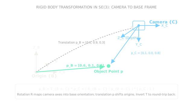
An overhead workspace camera observes a tabletop. The camera is rotated around the base -axis and translated by .
The rotation matrix maps camera axes:
- Camera aligns with base .
- Camera aligns with base .
- Camera (optical depth) aligns with negative base .
Construct the homogeneous matrix:
The camera detects a coffee mug at ( right, depth ).
Compute the mug position in robot base coordinates :
The mug sits at ( forward, left, above table base).
Verify the round trip using the inverse transform:
The round trip recovers the original camera observation exactly.
Code
This Python snippet builds the homogeneous transformation matrix, transforms the camera point to base frame coordinates, and verifies round-trip inversion using NumPy.
import numpy as np
def transform_point_se3( rotation_matrix: np.ndarray, translation_vector: np.ndarray, point_c: np.ndarray,) -> tuple[list[float], list[float]]: """Transform point from camera frame C to base frame B, then invert back.""" t_bc = np.eye(4) t_bc[:3, :3] = rotation_matrix t_bc[:3, 3] = translation_vector
# Homogeneous point [x, y, z, 1] p_c_homo = np.append(point_c, 1.0) p_b_homo = t_bc @ p_c_homo p_b = p_b_homo[:3]
# Invert transformation: T_cb = inv(T_bc) t_cb = np.linalg.inv(t_bc) p_c_recovered = (t_cb @ p_b_homo)[:3]
return [round(float(v), 3) for v in p_b], [round(float(v), 3) for v in p_c_recovered]
r_bc = np.array([ [1.0, 0.0, 0.0], [0.0, 0.0, -1.0], [0.0, 1.0, 0.0],])p_bc = np.array([0.5, 0.9, 0.3])pt_cam = np.array([0.1, 0.0, 0.8])
base_pt, recovered_pt = transform_point_se3(r_bc, p_bc, pt_cam)print(base_pt) # -> [0.6, 0.1, 0.3]print(recovered_pt) # -> [0.1, 0.0, 0.8]Watch Out For
Reversing transformation direction in matrix multiplication
A frequent bug is writing but multiplying vectors as if it were . Matrix multiplication is non-commutative ().
The symptom is the robot arm moving in the completely opposite direction from the detected object, or commanding extreme joint angles that hit software safety limits. Fix it by adopting a strict naming convention: name variables T_target_from_source or T_base_cam, and ensure that chained transforms cancel adjacent indices like dominoes: .
Overlooking extrinsic camera calibration drift
Mounting a depth camera to a robot's wrist (eye-in-hand) or overhead rig requires hand-eye calibration to determine the exact matrix . Over time, motor vibrations and physical bumps shift the camera mount by a fraction of a degree.
The symptom is grasping failures that gradually worsen over days: the camera sees the object clearly, but the gripper consistently misses by 1 to 2 centimeters. Fix it by running automated calibration routines using ArUco or ChArUco fiducial marker boards at regular maintenance intervals or startup.
The Quick Version
- Robotic systems maintain multiple coordinate frames: world , robot base , camera , and tool .
- Rigid body transformations belong to the Special Euclidean Group , composed of a rotation matrix and a translation vector.
- A homogeneous transformation matrix combines rotation and translation into a single linear matrix multiplication.
- Inverting an transformation uses the transpose of the rotation matrix () and , avoiding numerical matrix inversion.
- Strict notation () prevents fatal coordinate direction swaps during multi-camera and hand-eye transformations.