Degrees of Freedom and Robot Bodies
Degrees of freedom measure the independent parameters needed to specify a robot's physical configuration in space. A robot's configuration space dimension equals its actuated joints, while its operational task space is at most 6D (three positions and three orientations).
Why Does This Exist?
When commanding a robotic manipulator or mobile rover, you want to tell it where to place its tool or where to drive on the floor. But you cannot simply command arbitrary spatial targets: a robot cannot reach a point further than the sum of its limbs, cannot slide sideways if its wheels are locked forward, and cannot rotate its wrist through its own mechanical base.
Degrees of Freedom (DoF) provide the fundamental accounting system for robotic mechanics. They tell you:
- How many independent numbers are required to define the robot's complete posture.
- What physical volume of space the robot can actually reach (its workspace).
- Whether the robot has redundancy to maneuver around obstacles while holding a tool fixed.
Without this accounting, planners request impossible poses, policies command motions into self-collisions, and algorithms confuse joint space with task space.
Basics first: the electromechanical motors driving each degree of freedom live in robot-anatomy. How coordinates transform between the robot base and hand lives in robot-coordinate-frames. Solving for the exact joint angles that place the hand at a target lives in robot-forward-inverse-kinematics.
Think of It Like This
A train on a track versus a helicopter in the sky
A train rolling along a railway has 1 degree of freedom: its position along the track (a single distance coordinate ). Even though the track twists through a 3D mountain range, the train has no instantaneous choice to sidestep or climb without leaving the rails.
A helicopter hovering in open air has 6 degrees of freedom in 3D space: three translation coordinates (forward/back, left/right, up/down) and three rotation angles (roll, pitch, yaw).
A robot arm with 6 motorized joints is like a snake tethered to the ground: it can place its fingertip at any 3D position and orientation within reach. If you give it a 7th joint, it can keep its fingertip glued to the mug while swinging its elbow in an arc to avoid bumping into an adjacent cup.
Where it stops: a helicopter can fly anywhere within its fuel range, but a robot's joints have hard physical limits (e.g. ). Even with 6 or 7 motors, the robot's physical links sweep a bounded geometric envelope with internal holes and outer boundaries that cannot be crossed.
How It Actually Works
Configuration space (-space) versus Task space
To control a robot, we must distinguish between two different mathematical spaces:
- Configuration Space (-space): The space of all possible joint states. For an -joint serial arm with revolute joints, a single configuration is a vector of angles . The dimension of -space is exactly .
- Task Space (Operational Space): The space where the robot's physical task is specified, typically rigid-body poses in (dimension 6: position and roll, pitch, yaw orientation) or planar poses in (dimension 3: ).
When , the arm is underactuated for full 3D manipulation: it cannot achieve arbitrary poses. When , there is typically a finite set of discrete configurations that reach a given target pose. When , the arm is kinematically redundant: an infinite continuous manifold of arm postures can hold the exact same end-effector pose.
Holonomic versus nonholonomic systems
Having degrees of freedom in configuration does not mean you have independent velocity controls at any instant:
- Holonomic robots: Can instantly accelerate along all configuration coordinates. An omnidirectional mobile base with Mecanum wheels can translate sideways, drive forward, or spin in place instantaneously ( controllable velocity DoF in ).
- Nonholonomic robots: Suffer from differential motion constraints. A standard differential-drive mobile base or car has a 3D configuration , but only 2 control inputs (forward speed and turn rate ). It cannot slide sideways instantaneously (). Parallel parking requires maneuvering forward and backward because lateral velocity is constrained to zero.
Worked example: workspace of a 2-link planar arm
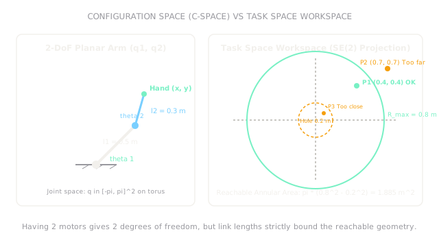
Consider a planar arm moving in the -plane with two revolute joints and rigid links of lengths and .
- Joint space: (a 2D torus).
- Task space: Target end-effector coordinates .
The maximum reach occurs when the arm is fully extended ():
The minimum reach occurs when the second link folds fully back along the first link ():
The reachable workspace is an annulus (ring) centered at the base origin . Its surface area is:
Now evaluate reachability for three candidate target points:
- Target : Since , target is reachable inside the annular workspace.
- Target : Since , target is unreachable (lies beyond maximum reach).
- Target : Since , target is unreachable (lies inside the central inner singularity hole).
Code
This Python snippet defines the 2-link arm kinematics boundaries, computes the workspace area, and tests candidate Cartesian targets for geometric reachability.
import math
def check_planar_reachability( l1: float, l2: float, points: list[tuple[float, float]],) -> tuple[float, float, float, list[bool]]: """Compute workspace limits, annular area, and evaluate reachability of points.""" r_max: float = l1 + l2 r_min: float = abs(l1 - l2) area: float = math.pi * (r_max ** 2 - r_min ** 2)
reachability: list[bool] = [] for x, y in points: dist: float = math.hypot(x, y) reachability.append(r_min <= dist <= r_max)
return round(r_max, 3), round(r_min, 3), round(area, 3), reachability
r_max, r_min, area, results = check_planar_reachability( l1=0.5, l2=0.3, points=[(0.4, 0.4), (0.7, 0.7), (0.1, 0.1)],)
print(r_max) # -> 0.8print(r_min) # -> 0.2print(area) # -> 1.885print(results) # -> [True, False, False]Watch Out For
Assuming actuator count equals instantaneous control degrees of freedom
A common mistake is believing that because a wheeled delivery rover has 4 driven wheels, it can drive in any direction instantaneously. If the wheels are standard fixed rubber tires (differential drive or Ackermann steering), the robot is nonholonomic.
The symptom is commanding a planner to move sideways into a tight charging dock, causing wheel scrubbing or failed trajectory tracking. Fix it by formulating motion planners in the robot's actual kinodynamic state space rather than unconstrained Cartesian space.
Ignoring the inner workspace singularity hole
When link lengths are unequal (), the arm cannot fold onto its own base: it has a circular blind zone of radius where the tool tip can never reach.
The symptom is inverse kinematics solvers hanging, throwing numerical divide-by-zero exceptions, or commanding joints to rotate at infinite velocity when a user requests an object close to the robot's mounting base. Fix it by checking radial bounds () before passing goals to the kinematic solver.
The Quick Version
- Degrees of freedom (DoF) represent the minimum number of independent coordinates needed to uniquely describe a robot's physical configuration.
- Configuration space (-space) has dimension equal to the number of joints, whereas task space is the 3D () or planar () environment.
- A 2-link planar arm () sweeps an annular workspace with outer radius and inner unreachable hole , enclosing .
- Holonomic systems can accelerate along all coordinates instantaneously; nonholonomic systems (like cars and differential rovers) have velocity constraints that prohibit sideways sliding.
- Redundant manipulators () can reconfigure internal joint postures (elbow angles) while holding the end-effector perfectly still.