Robot Actuator Limits: Torque, Speed and Heat
A motor can supply a requested torque only at speeds, currents and temperatures its hardware permits. More gearing changes those limits rather than removing them.
Why Does This Exist?
An arm holds its payload at rest, then falls behind during a fast lift. The motor may have enough low-speed torque but insufficient voltage to maintain that torque while spinning. Actuator limits describe the feasible combinations of effort, speed and operating time at a joint. A single maximum-torque number cannot describe them.
Torque is turning effort in newton metres; angular speed is rotation per second in radians. Their product is mechanical power in watts. Robot anatomy introduces motors and transmissions. Here we calculate the envelope against which dynamics must check its torque requests. The calculation uses a permanent-magnet DC equivalent, not a specification for an arbitrary brushless drive.
Think of It Like This
Changing gears on a bicycle
A low gear lets your legs turn faster while the wheel turns more slowly, increasing wheel torque for the same pedal torque. It does not increase the power your legs can sustain. A short hard sprint is also different from a climb you must maintain. Gear ratio maps to speed and torque conversion; sustained effort maps loosely to a continuous rating. The analogy stops at the motor's electrical constraint: bicycle legs have no winding resistance or back electromotive force.
How It Actually Works
Why does torque disappear at high speed?
In the steady-current DC model, motor torque is and terminal voltage is . Current is in amperes, winding resistance in ohms, is the torque constant in Nm/A, the voltage constant in V s/rad, and motor speed in rad/s. Rotation produces the opposing voltage . Current transients add inductance times the rate of current change; we omit that term only for this steady-current envelope. Northwestern's motor equations derive these relationships and distinguish continuous current from stall current.
For positive-speed motoring with supply cap and current cap ,
The outer maximum describes our nonnegative motoring current, not regenerative braking. With reduction and assumed motoring efficiency , joint torque is . Joint speed is . The transmission power balance explains why reduction exchanges speed for torque and why losses reduce output. At standstill, the constant efficiency factor is only an assumed torque-loss approximation; the output-to-input mechanical power ratio is undefined.
Compute the same operating point three ways
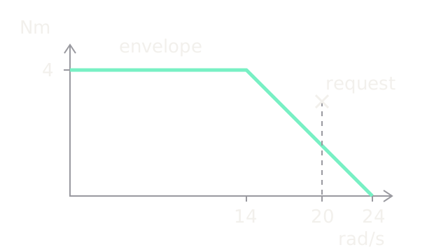
Take hypothetical values V, ohms, in the SI units above, A, and . These are a teaching fixture. The current-limited output cap is Nm. Voltage becomes limiting when , giving rad/s. At 20 rad/s the motor turns at 200 rad/s; back EMF is 20 V, leaving 4 V across the resistance. Current is 2 A and output torque is only 1.6 Nm.
A 3 Nm request at that speed requires A, below the current cap, but V, above the supply cap. Checking current alone accepts an impossible request. At 24 rad/s the idealized motoring torque reaches zero; real friction lowers attainable no-load speed. The diagram draws this piecewise cap, and the crossed request above it, on joint-side axes.
What changes when a motion repeats?
Copper heating follows , so mean current hides alternating high loads. For a short repeating cycle relative to thermal response, use , where is each time fraction and the fractions sum to one. Five-amp pulses with zero current between them give 2.5 A RMS at 25% duty and about 3.536 A at 50%. An assumed 3 A continuous allowance passes the first screening and fails the second. Pulse length, cooling and peak ratings still need separate checks; RMS alone does not establish safe winding temperature.
Reduction also reflects rotor inertia as , where is rotor inertia. This follows by rewriting rotor kinetic energy in joint coordinates, as in Modern Robotics 8.9. Higher reduction buys effort at lower speed but increases that acceleration burden and often reduces backdrivability. A counterbalance or a slower trajectory can be better than more gearing when gravity or speed is the binding constraint.
Code
This standalone Python checks both electrical constraints and a repeating duty cycle. It does not model current-loop transients, gearbox ratings or temperature.
from math import sqrt
def joint_cap(speed: float) -> float: if speed < 0: raise ValueError("This example covers positive-speed motoring only") current = max(0.0, min(5.0, (24.0 - speed) / 2.0)) return 0.8 * current
for speed in (0.0, 14.0, 20.0, 24.0): print(f"{speed:.0f} rad/s: {joint_cap(speed):.1f} Nm")required_current = 3.0 / 0.8assert required_current < 5.0assert 2.0 * required_current + 20.0 > 24.0for duty in (0.25, 0.5): rms = sqrt(duty * 5.0**2) print(f"duty {duty:.2f}: {rms:.3f} A, continuous check {rms <= 3.0}")Output torque caps are 4.0, 4.0, 1.6, 0.0 Nm. The duty checks print
2.500 A, continuous check True and 3.536 A, continuous check False.
Watch Out For
A constant torque clamp admits impossible fast motion
Tracking fails only near high speed although the requested current is below its cap. Evaluate speed-dependent voltage headroom along the trajectory. Retiming reduces speed and acceleration demand; increasing feedback gains supplies no additional voltage. Driver bus limits and measured supply sag belong in this check.
A peak rating becomes a continuous holding command
The arm holds initially, then derates or trips. At zero speed, mechanical output power can be zero while winding heat is substantial. Check continuous current, thermal response and cooling. For brushless hardware, align phase/line and RMS/peak conventions with the manufacturer's torque constant before using this DC equivalent.
The Quick Version
- Current limits bound low-speed torque; back EMF consumes voltage headroom at speed.
- The example's 3 Nm request at 20 rad/s needs 27.5 V despite needing less than 5 A.
- Reduction exchanges torque for speed and reflects rotor inertia by the squared ratio.
- RMS current screens repeating copper heating; peak and thermal-transient limits remain separate.
- A feasible motion must satisfy actuator constraints throughout its execution.