Robot Dynamics: Forces, Inertia and Torque
A pose tells you where an arm is. Its inertia, gravity and external loads determine how much torque the motors need to hold it there or change its motion.
Why Does This Exist?
An empty gripper tracks a motion. Add a payload and the same motion lags or saturates the drive. Its geometry hasn't changed, but accelerating and supporting the body requires more torque. Robot dynamics relates forces and torques to acceleration, accounting for inertia, gravity and interaction with the environment.
A force pushes along a direction, in newtons. A torque tends to rotate about an axis, in newton metres; a force applied perpendicular to a lever produces torque equal to force times lever length. Robot anatomy connects motor current, gearing and joint output. Here torque means joint-side output, after the transmission, rather than an arbitrary driver command.
Kinematics answers where the tool goes for a configuration. Dynamics asks whether the actuator can produce the motion, and what happens when the delivered torque differs from the request. These questions remain relevant when a learned policy chooses the target.
Think of It Like This
Holding a shopping bag at arm's length
A bag pulls downward even while your hand stays still. Hold it farther from your shoulder and its turning effect increases. Start lifting and you need additional effort to accelerate it; start lowering and gravity helps the motion. Its position, weight and changing speed all matter.
Your shoulder's effort maps to joint torque, the bag's weight to gravity load and its resistance to acceleration to inertia. The analogy stops at the body model: your arm has distributed mass and many muscles, whereas our worked arm has one ideal torque source and a massless link carrying a point payload.
How It Actually Works
What does the manipulator equation account for?
For a fixed-base, fully actuated rigid arm with joint positions , a common convention is
Dots denote time derivatives. The mass matrix maps joint acceleration to inertial torque. The vector contains Coriolis and centrifugal terms from moving links; is the torque required to balance gravity. The friction model is written on the left as a resisting load. Applied motor torque is . is the environment's wrench on the tool, and is the matching Jacobian. An inward pushing environment load and the robot's outward applied load have opposite signs.
For independent physical coordinates with nonzero inertia, is symmetric positive definite. Its off-diagonal entries describe coupling: accelerating one joint may require torque at another. It is neither a list of link masses nor generally constant. MIT's multibody dynamics notes derive the manipulator form from kinetic and potential energy, using a different placement of the gravitational force. Changing sides changes its sign.
Derive one joint instead of memorizing a torque budget
Consider a massless rigid link of length rotating in a vertical plane with a point payload of mass . Measure angle counterclockwise from vertically downward; positive torque increases . The payload position is . Its speed is , so kinetic energy is . Potential energy is , taking zero height at the pivot and gravitational acceleration m/s².
With no friction or other contact, differentiating these energies gives
Here is rotational inertia in kg m². The constant-inertia single joint has no velocity-coupling term; that does not remove such terms from a multi-link arm. Modern Robotics' Lagrangian derivation explains this energy-based route to the equations.
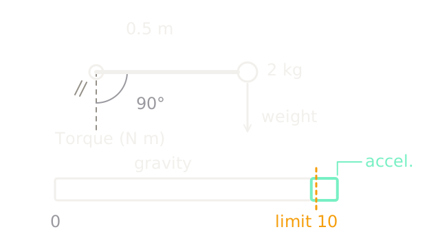
Set kg, m and , so the link points horizontally right. Then kg m². The downward payload force is N and the gravity-balancing torque is N m. Requesting rad/s² adds N m, for a total of 10.81 N m.
The diagram's torque bar uses one shared length scale. Its long outlined segment is the 9.81 N m support load; the short mint segment is the additional 1 N m for acceleration. The downward arrow at the payload shows weight direction. It uses no shared scale with the torque bar, since force and torque have different units.
What happens at the actuator limit?
Suppose delivered positive joint torque is capped at 10 N m. At this exact posture,
Only 0.19 N m remains for acceleration. The command is only 0.81 N m over the cap, yet achievable acceleration falls from 2 to 0.38 rad/s². Near a gravity limit, a small torque shortfall can remove most of the motion budget. With an 8 N m cap, acceleration would be rad/s²: the load initially falls even under maximum positive torque. These are instantaneous predictions at the horizontal posture, not constant accelerations throughout a falling trajectory.
Inverse dynamics evaluates the required torque for a desired acceleration. Forward dynamics solves the same equation for acceleration given delivered torque. In a general arm, solve a linear system with rather than explicitly inverting it. Modern Robotics on forward dynamics separates this acceleration solve from numerical integration over time.
How should a controller use the model?
Gravity feedforward supplies the estimated holding load before feedback asks for motion correction. Inverse-dynamics feedforward also includes the acceleration and velocity-dependent terms. Feedback still corrects mismatch; a wrong payload or friction estimate survives the algebra.
The mass-matrix discussion in Modern Robotics shows how posture changes directional inertia. A planner must evaluate that changing load along its path, rather than declaring the whole trajectory feasible from one holding test. Slowing a motion reduces inertial demands, but cannot remove an unachievable static gravity load.
Use a detailed dynamics model when torque feasibility or contact response affects the decision. For a slow geometric reach query, a kinematic model may be enough. The additional parameters and calibration effort should buy a prediction you actually need; system identification explains how to estimate those parameters from data.
Code
This scalar check keeps inverse dynamics, actuator saturation and forward dynamics separate. It is an offline calculation, not an arm driver.
from math import sin, pi
def required_torque(m: float, length: float, q: float, accel: float) -> float: return m * length**2 * accel + m * 9.81 * length * sin(q)
def acceleration(m: float, length: float, q: float, delivered: float) -> float: return (delivered - m * 9.81 * length * sin(q)) / (m * length**2)
request = required_torque(2.0, 0.5, pi / 2, 2.0)delivered = min(request, 10.0)actual = acceleration(2.0, 0.5, pi / 2, delivered)assert abs(request - 10.81) < 1e-12assert abs(actual - 0.38) < 1e-12assert acceleration(2.0, 0.5, pi / 2, 8.0) < 0print(f"requested={request:.2f} N m, delivered={delivered:.2f} N m")print(f"acceleration={actual:.2f} rad/s^2")Output: requested=10.81 N m, delivered=10.00 N m and acceleration=0.38 rad/s^2.
Link mass, transmission inertia, friction and torque-speed dependence are omitted.
Watch Out For
The payload changes but the gravity model does not
The arm droops after a grasp despite tracking well when empty. Check the payload mass and center of mass used by the controller, and distinguish their error from friction or a joint offset. Increasing integral gain can conceal the support mismatch while consuming torque headroom. Confirm the load model and delivered torque first.
A requested torque is treated as a measured torque
Predicted acceleration looks correct while the joint lags at high speed. A software request may pass through current, thermal, voltage and drive limits before becoming joint torque. Use the relevant delivered-effort estimate, its calibration and the drive's active limit state. Replaying the raw request into a simulator hides saturation.
The Quick Version
- Dynamics predicts acceleration from forces and torques, rather than position from joint angles.
- The mass matrix includes posture-dependent coupling between joints.
- Inverse dynamics computes a torque request; forward dynamics uses delivered torque to compute acceleration.
- Supporting gravity consumes torque even at zero speed, and slower motion cannot fix insufficient holding torque.
- Model-based control still depends on calibrated parameters, feedback and actuator limits.