Differential-Drive Odometry
Two wheel encoders measure travel along two arcs. Their average gives axle travel; their difference gives turning, so the robot's displacement follows a curve.
Why Does This Exist?
A mobile base turns through a doorway, but its software adds the average wheel distance to world x. The resulting pose is wrong even with perfect encoders. Differential-drive odometry integrates two wheel rotations into position and heading under a rolling-without-slip model. It estimates relative motion; it cannot identify a wheel slipping against the floor from encoder travel alone.
The chassis pose is : two positions and heading. As degrees of freedom explains, three pose coordinates do not supply an instantaneous sideways control. Odometry generates the motion increments that state estimation can fuse with independent sensing. It does not replace that estimator or a global map.
Think of It Like This
Two people carrying the ends of a straight pole
To turn while keeping the pole rigid, the outside person walks farther than the inside person. Both follow arcs around one turning center. The pole's midpoint also follows an arc; its travelled distance exceeds the straight chord between start and finish. The pole maps to the axle and the walkers to the wheel contacts. The analogy assumes a smooth coordinated turn: real people can sidestep, while ideal conventional wheels cannot roll sideways.
How It Actually Works
How do wheel distances determine turning?
Let wheel separation be metres, wheel radii , and encoder changes in radians. Distances are and , positive for forward rolling. Define x forward at initial heading zero, y left, and positive heading counterclockwise viewed from above. Then
If forward speed is and turn rate , the continuous model is , , . There is no independent lateral velocity. The Modern Robotics nonholonomic model derives that constraint and shows that wheel-speed bounds constrain combinations of forward and turning speeds, rather than providing two unrelated chassis limits.
Integrate a curve instead of a heading snapshot
Assume constant wheel velocities during the integration interval, or equivalently constant curvature over the measured travel. For a nonzero turn, midpoint radius is . Starting from heading ,
Add these increments to position and add to heading. When the turn is tiny, avoid dividing two small quantities. Equivalently use
where and . This is the unnormalized sinc: some numerical libraries put a factor of pi inside their function. Averaging headings gives the chord's direction, but omitting sinc uses arc length as chord length. Small increments reduce this approximation error; they do not remove slip error.
Work a quarter-turn example
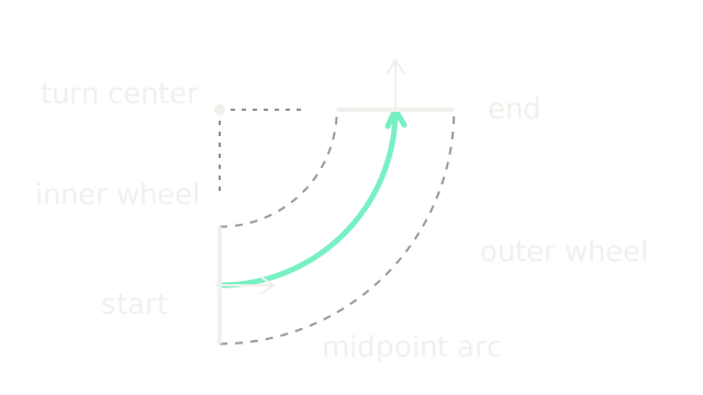
Take m, m and m, starting at . Mean travel is m, heading change is , and radius is m. Thus m and m. The inner and outer wheel radii are and m, which give the specified quarter-circle distances. The SVG shows these concentric paths on an equal metric scale, with the solid midpoint arc between dashed wheel arcs. Short arrows show initial and final heading.
Initial-heading Euler integration would give , an endpoint miss of about 0.690863 m. That deliberately large interval exposes the geometric mistake. A changing wheel-speed ratio needs smaller time-aligned increments; final encoder totals alone do not reconstruct the order of turns and straight segments.
Where does drift enter?
An incorrect wheel radius scales measured travel; unequal effective radii create heading bias even during nominal straight driving. Track-width error biases turns. Slip violates the underlying relation between rotation and ground travel. The Modern Robotics odometry chapter treats pose as accumulated motion, which explains why such errors persist.
Encoders are cheap and available without scene texture, but their integrated pose drifts. Calibrate geometry against independent distance and rotation observations, then fuse independent measurements. Visual or range-based localization can correct drift when the scene provides constraints; wheel encoders remain useful through brief visual failures. Do not interpret an exact no-slip update as exact physical pose.
Wheel travel and inertial sensing fail in different ways. Inertial navigation explains the gravity and bias model needed before IMU readings can complement this estimate. To turn an estimated pose and a planned route into wheel-speed requests, path tracking derives a lookahead controller.
Code
This standalone update handles straight motion and in-place turns without dividing by total turn angle. The final comparison isolates integration error, not slip.
from math import cos, sin, pi, hypot
def advance(pose: tuple[float, float, float], left: float, right: float, width: float) -> tuple[float, float, float]: if width <= 0: raise ValueError("Wheel separation must be positive") x, y, heading = pose distance = (left + right) / 2.0 turn = (right - left) / width a = turn / 2.0 sinc = 1.0 - a*a/6.0 if abs(a) < 1e-6 else sin(a)/a chord = distance * sinc return (x + chord*cos(heading+a), y + chord*sin(heading+a), heading+turn)
x, y, angle = advance((0.0, 0.0, 0.0), 0.2*pi, 0.4*pi, 0.4)print(f"pose: {x:.6f}, {y:.6f}, {angle:.6f}")print(f"Euler miss: {hypot(0.3*pi-x, y):.6f} m")assert advance((0.0, 0.0, 0.0), 0.1, 0.1, 0.4) == (0.1, 0.0, 0.0)spin = advance((0.0, 0.0, 0.0), -0.1, 0.1, 0.4)assert spin == (0.0, 0.0, 0.5)Output pose is 0.600000, 0.600000, 1.570796; the Euler miss is
0.690863 m.
Watch Out For
The robot turns the wrong way in its map
A physical left turn decreases estimated heading. Verify encoder polarity, wheel assignment and the heading convention before tuning a filter. Under this page's convention, greater right-wheel travel increases heading. Swap or negate signals at their source contract, rather than patching the map display.
Exact integration is mistaken for a slip detector
The encoder trajectory is smooth while the base remains stuck or skids. An exact arc integrates the assumed motion, including false travel. Compare independent inertial or exteroceptive observations and represent uncertainty; increasing update frequency alone cannot reveal wheel-ground slip.
The Quick Version
- Mean wheel travel sets axle travel; wheel-travel difference divided by separation sets turning.
- The no-slip differential-drive model has no independent instantaneous lateral velocity.
- Exact arc integration gives the example endpoint m after a quarter turn.
- A sinc formulation handles the straight-motion limit without unstable division.
- Encoder odometry needs calibrated geometry and independent observations to limit drift.