Legged Robot Balance and the Capture Point
Standing over a foot is not enough when the body is moving. Position and velocity together determine where support must act to arrest a fall in a simple walking model.
Why Does This Exist?
A robot's center of mass projects inside its foot, but a shove gives it enough forward speed to fall anyway. Dynamic balance depends on velocity and available contact forces, not just a snapshot of body position. The capture point gives a precise stopping-support location for a restricted inverted-pendulum model.
The center of mass, or CoM, is the mass-weighted average position of the body. The center of pressure, or CoP, is the location of the resultant normal contact load on a supporting plane. On flat ground with nonnegative pressure, CoP lies inside the supporting contact area. Robot dynamics relates those forces to motion; contact friction limits which forces the floor can provide. Here we derive a balance model for use by a controller, rather than another generic MPC optimizer.
Think of It Like This
Catching a broom balanced on your palm
A broom can be upright over your hand and still be moving toward a fall. Move your palm ahead of the broom's motion so support can slow it, then bring the two to rest together. The broom's body maps to CoM, the palm to support location, and the necessary lead to the velocity-dependent capture offset. The analogy stops at the model: a broom rotates and changes its mass height, while the calculation below uses a constant-height point mass and neglects body angular-momentum changes.
How It Actually Works
Why does the center of pressure matter?
In static equilibrium on a horizontal plane, with gravity and contact as the only external loads, CoM projection and resultant CoP coincide. The support polygon is the convex hull of supporting areas. A projection inside it permits static equilibrium under ideal force and actuation assumptions; it does not prove that the current moving state can stop there. Contact changes, friction and actuator limits can further reduce feasible support. The legged-robot modeling chapter develops these contact and balance relationships and explains the assumptions behind reduced models.
Derive the constant-height model
Let horizontal CoM position be metres, constant CoM height metres and CoP position metres, all in a world frame. Let m/s². Assume a point mass, flat ground, zero vertical acceleration and no change in angular momentum about CoM. Vertical contact force then balances weight. Taking moments gives , and horizontal force balance gives . Therefore the linear inverted pendulum model is
Dots mean time derivatives, is net horizontal ground force and is mass. Frequency has units s⁻¹. If CoM lies ahead of CoP, acceleration points farther forward. This is an unstable inverted pendulum: returning a moving CoM requires placing support appropriately, not simply holding the same foot-center force.
Define . Differentiating and substituting the dynamics gives . For constant , any initial grows exponentially. Set and the growing mode vanishes; then
Velocity tends to zero and CoM tends to support position. Thus is the capture point for this model. Pratt and colleagues' capture-point paper derives capture behavior and extends the point-mass model with angular momentum. The formula is a conditional stopping result, not a universal location where a full humanoid can safely place a foot.
Compute a state that looks statically safe
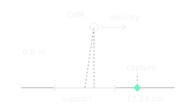
Take m, m and forward speed m/s. Let the current support interval be m about foot center. Then s⁻¹ and
CoM projection is inside the foot, but capture point is about 7.28 cm beyond the forward edge. In this fixed-height, no-angular-momentum model, current support cannot arrest the state without changing the support region. At the forward edge , CoM acceleration is initially m/s²: it brakes initially, yet that alone does not cancel the unstable component.
If the simplified model could place CoP instantly at m, after one second its CoM would be about 0.168480 m and its speed about 0.015072 m/s. The required initial horizontal force relative to vertical force is , so an assumed coefficient passes the initial friction check. This does not check joint torque or stepping reachability.
The SVG's horizontal geometry is measured: CoM projection is at 3 cm, support ends at 10 cm and the diamond at 17.28 cm. Vertical scale is compressed relative to x for the side-view schematic, so the drawn leg angle is not a force-angle measurement. The velocity arrow shows direction only. No future foot is drawn: the capture location itself may be unreachable in time.
What changes for a real walking robot?
A swing foot cannot teleport. While it moves, the capture state evolves. With fixed current CoP, , so a target computed before a delayed step can already be obsolete when contact occurs. Reach limits, swing time, obstacles and impact all matter. MPC can plan support over time using this model, but its execution still needs whole-body force and joint control.
The linear model is economical and exposes unstable motion directly. Variable height, uneven terrain or substantial arm/torso momentum can make its assumptions inadequate; centroidal or full-body dynamics cost more computation but retain those effects. The support polygon is still useful for static tasks, and capture point is useful for this dynamic approximation. Neither substitutes for friction, actuation and contact-timing checks.
Code
This standalone Python verifies the captured trajectory against the analytic solution. The assumed instantaneous support placement isolates the model's mechanism.
from math import sqrt, exp
def capture(x: float, velocity: float, height: float) -> float: if height <= 0: raise ValueError("Height must be positive") return x + velocity / sqrt(9.81 / height)
x0, v0, height = 0.03, 0.5, 0.8omega = sqrt(9.81 / height)p = capture(x0, v0, height)print(f"capture {p:.6f} m, inside foot {-0.1 <= p <= 0.1}")t = 1.0x = p + (x0-p)*exp(-omega*t)v = -omega*(x0-p)*exp(-omega*t)assert abs(capture(x, v, height)-p) < 1e-12print(f"after 1 s: x {x:.6f} m, speed {v:.6f} m/s")print(f"required initial friction ratio: {abs(x0-p)/height:.6f}")Output starts capture 0.172784 m, inside foot False. At one second it prints
x 0.168480 m, speed 0.015072 m/s; the initial friction ratio is 0.178480.
Watch Out For
An inside CoM projection is treated as a stopping guarantee
The robot passes a static support check but continues to fall after a push. Include velocity in the state and evaluate dynamic contact feasibility. In the fixture, even maximum forward CoP cannot remove the unstable mode under this restricted model. More accurate position sensing alone cannot repair an omitted velocity state.
The foot lands at an old capture point
A computed recovery point was reachable when selected but fails after a long swing. Propagate the capture state through the swing interval and account for landing time and reachable footholds. Check friction and torque after touchdown. A full-body recovery may also use changing height or momentum, which this model intentionally omits.
The Quick Version
- Dynamic balance depends on CoM position, velocity and available contact actions.
- Constant-height inverted-pendulum dynamics give capture point .
- The example projects inside the foot but has a capture point 17.28 cm ahead of center.
- Capture-point stopping assumes feasible support placement and the stated reduced dynamics.
- Swing timing, friction, actuator limits and momentum changes determine real recovery capability.