Robot Simulation and Physics
Simulators provide parallel, risk-free environments to train and test robots, but physics engines must discretize continuous equations of motion, solve rigid-body contact complementarity, and approximate friction, introducing artifacts that do not exist in reality.
Why Does This Exist?
Training a robot reinforcement learning policy or vision-language-action model requires millions of interaction steps. If you attempted to collect those trials exclusively on physical hardware, robotic arms would wear out their gearboxes, quadruped robots would break limbs falling down stairs, and data collection would take years of manual battery swapping.
Physics simulation makes robot learning practical: a cluster of GPUs running massively parallel environments (like Isaac Gym or MuJoCo) can generate years of simulated physical experience in hours.
However, a simulator is not reality. A physics engine is a discrete numerical approximation of continuous Newtonian mechanics. It must solve differential equations in discrete time steps , approximate non-smooth contact friction, and detect geometric collisions between polygonal meshes. If an algorithm overfits to the simulator's computational shortcuts, it fails the moment it is loaded onto real physical hardware.
Basics first: the sim-to-real gap and domain randomization theory live in sim-to-real-transfer. Reinforcement learning algorithms that train inside simulators live in robot-reinforcement-learning. Deploying verified policies safely to real hardware lives in robot-policy-deployment.
Think of It Like This
A flight simulator versus an authentic aircraft cockpit
Imagine practicing crosswind landings in a commercial flight simulator. The hydraulic motion base rolls and pitches, the panoramic screens display rain, and the cockpit controls feel convincing.
If the simulator's aerodynamic code rounds off ground-effect airflow turbulence to maintain 60 frames per second, you might learn to touch down smoothly with minimal rudder. But when you climb into a real twin-engine aircraft and drop toward the runway, real air vortices cushion and bounce the wings unpredictably.
Where it stops: in aviation, fluid mechanics in free air are relatively smooth and continuous. In robotics, physical manipulation involves non-smooth contact: hard steel fingers colliding with rigid ceramic mugs, stick-slip friction, and micro-impacts. Simulators must approximate these discontinuous contact events using mathematical complementarity solvers that can produce unphysical artifacts like object interpenetration and explosive bouncing.
How It Actually Works
The rigid-body dynamics pipeline
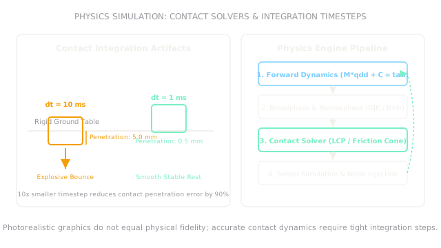
Every simulation step advances the physical world through four tightly coupled phases:
- Forward Dynamics: Integrates the equations of motion (the Manipulator Equation): where is the inertia matrix, captures Coriolis and centrifugal effects, is gravity, is motor torque, and represents contact wrenches.
- Collision Detection: Broadphase uses bounding volume hierarchies (BVH) to prune distant pairs; narrowphase uses algorithms like Gilbert-Johnson-Keerthi (GJK) and Expanding Polytope Algorithm (EPA) to determine contact points and penetration depths.
- Contact Constraint Solving: Enforces non-penetration and Coulomb friction cones. Because rigid bodies cannot interpenetrate, contact is formulated as a Linear Complementarity Problem (LCP): where is normal separation distance and is normal contact force. Either distance is zero (in contact, force ) or force is zero (separated, distance ).
- Numerical Integration: Advances positions and velocities forward by timestep using Semi-Implicit Euler or Runge-Kutta integration: \mathbf{q}}_{t+1} = \mathbf{q}_t + \Delta t \, \dot{\mathbf{q}}_{t+1}
Timestep selection and penetration depth
In discrete simulation, continuous motion is evaluated at intervals . If a rigid object moves at impact velocity toward a surface, it moves a discrete distance during one step before collision detection runs.
In penalty-based contact models, restoring force is proportional to penetration: . If is too large, the object penetrates deeply into the floor before the engine detects it. The resulting restoring force is artificially massive, injecting non-physical energy and causing objects to explode off the ground.
Worked example: contact penetration at 10 ms versus 1 ms
A rigid block falls toward a table, reaching an impact velocity ():
-
Case 1: Large timestep (, typical for fast video games):
The block sinks into the solid table before the contact solver detects the collision. If surface stiffness , the restoring spring force spikes instantly to , kicking the block into an unphysical high-velocity bounce.
-
Case 2: Tight integration timestep (, standard in robotics physics engines):
The penetration is bounded to just ( reduction). The contact force remains smooth (), allowing contact damping to dissipate kinetic energy naturally without explosive bouncing.
Code
This Python snippet simulates 1D discrete penalty contact integration under two different timesteps, calculating penetration depth, contact restoring force, and illustrating numerical stability.
def simulate_impact_step( v_impact: float, dt: float, stiffness: float = 10000.0,) -> tuple[float, float]: """Compute 1-step contact penetration (mm) and restoring force (N).""" penetration_m: float = v_impact * dt penetration_mm: float = penetration_m * 1000.0 restoring_force_n: float = stiffness * penetration_m return round(penetration_mm, 2), round(restoring_force_n, 1)
# Compare 10 ms timestep vs 1 ms timesteppen_10ms, force_10ms = simulate_impact_step(v_impact=0.50, dt=0.010)pen_1ms, force_1ms = simulate_impact_step(v_impact=0.50, dt=0.001)
print(pen_10ms) # -> 5.0print(force_10ms) # -> 50.0print(pen_1ms) # -> 0.5print(force_1ms) # -> 5.0Watch Out For
Confusing photorealistic rendering with physical contact fidelity
Modern graphics engines (like Unreal Engine) can render stunning, cinema-quality visuals with ray-traced shadows and realistic reflections. However, visual rendering has zero correlation with physical contact fidelity.
The symptom is training a grasping policy in a gorgeous simulator that succeeds 99% of the time, then discovering on real hardware that the gripper cannot hold an object because the simulator modeled friction as an isotropic constant without torsional friction. Fix it by prioritizing physics engines optimized for contact complementarity (such as MuJoCo, Drake, or PhysX 5) rather than prioritizing rendering visuals alone.
Setting integration timesteps too large to boost throughput
When training reinforcement learning policies in parallel, it is tempting to set the physics timestep to or to maximize frames per second.
The symptom is policies learning "simulator exploits": quadrupeds discovering that slamming their feet into the ground at specific angles triggers numerical energy injection, allowing them to levitate or skate without realistic friction. Fix it by decoupling simulation substeps: integrate physics at () using or substeps per policy action cycle ().
The Quick Version
- Robot simulation enables parallel, accelerated, and risk-free data collection for reinforcement learning and policy verification.
- Physics engines approximate continuous dynamics through discrete numerical integration, collision detection, and contact complementarity solvers.
- An impact velocity of with a timestep causes of artificial penetration; cutting to reduces penetration to .
- Photorealism is distinct from physical fidelity: accurate mass matrices, contact wrenches, and friction cones govern sim-to-real success before robot policy deployment to physical hardware.
- Decoupling high-frequency physics substeps () from policy decision steps () prevents numerical instability and simulator exploits.